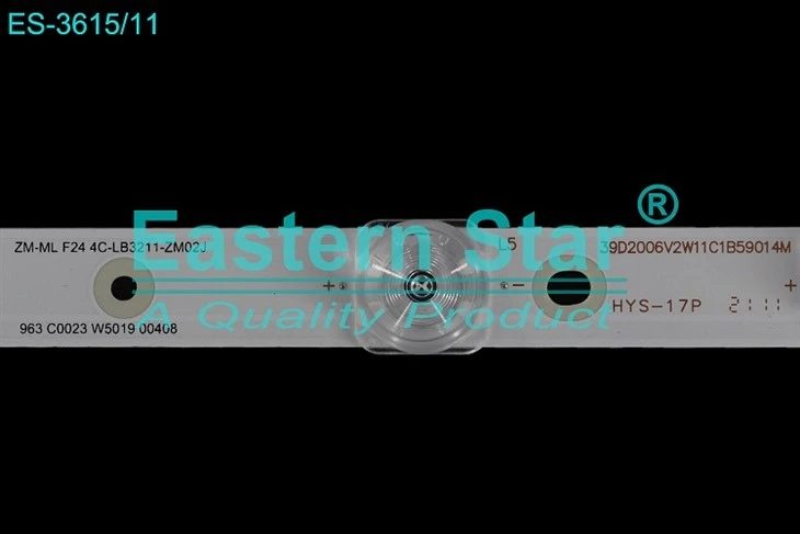
Q: TCL LCD TV L32F3301B filament voltage 41V backlight does not light up, how to solve it?
A: To make sure that the backlight tube of the TV is not faulty, if it is not faulty, it should be incorrect voltage. That is, the input voltage is not correct.
Also look at what the output voltage of the power on.
1, the monitor does not power the entire machine
(1) power supply failure: This is a should be said to be very simple failure, general LCD monitor power supply and power supply in the machine two kinds of power supply, outside of the machine some common. Regardless of the kind of power supply, its structure is much simpler than the crt monitor power supply, fragile is generally a number of small components, such as fuse, rectifier bridge. Power supply board commonly used ic: 6841203d06, these commonly used pmw chip in my professional LCD parts store can buy.
(2) drive board failure: drive board burn insurance or voltage regulator chip failure, some machines are switching power supply built-in, the output of two power supply, one of which is 5V, for signal processing, the other is 12V to provide high-voltage board point backlighting, if the switching power supply part of the circuit failure may lead to the two power supply are not output.
First check the 12V voltage is normal or not, followed by checking the 5V voltage is normal or not, because the A/D driver board MCU chip's operating voltage is 5V, so find the failure to turn on the machine, first use a multimeter to measure the 5V voltage, if there is no 5V voltage or 5V voltage has become very low, then a possibility is that the power supply circuit input stage problems, that is, 12V converted to 5V power supply part of the problem!
If there is no 5V voltage or the 5V voltage becomes low, then one possibility is that there is a problem in the input stage of the power supply circuit, that is to say, there is a problem in the 12V to 5V conversion part of the power supply.
2, another possibility is that the 5V load aggravation, the 5V voltage is very low, another way of saying that the signal processing circuit of the back stage of the problem, part of the circuit is damaged, resulting in load aggravation, the 5V voltage is very low, one by one to check the back stage of the problem components, replacement of faulty components, the 5V can be restored to normal, the problem is generally solved, but also often encountered the 5V voltage is restored to normal! After the 5V voltage returns to normal, but also can not be normal power on, this situation also has a variety of reasons, on the one hand, the MCU program is flushed out may lead to not power on, there is also the MCU itself is damaged, such as MCU I/O port damage, so that the MCU can not scan the keys, encountered this kind of failure caused by the MCU to look for the hardware problem is useless, even if you change the MCU can not solve the problem, because the MCU is the need to program and write code, in the absence of the MCU, the MCU can not be programmed and write code. Programming and writing code, there is no way to find the original AD driver board to replace the case, we can only use the general A/D driver board replacement, such as: 151D or 161B, etc. 2, the display is bright for a while on the light, but the power indicator green light is always on This problem is generally caused by high-voltage anomalies, is the protection circuitry action, in this case, the general LCD screen is displayed, the method of looking at the "squint! The way to see is to "squint".
3, the display black screen, no backlight, power light green light is always on) oblique view LCD screen has a display image, mostly belongs to the high-voltage board power supply circuit problems. Focus on checking the 12V power supply (fuse F) and 3V or 5V switching voltage is normal. If the MCU problem caused by the lack of output switching control voltage, you can directly extract the 3-terminal voltage regulator block (AIC1084) 3.3V instead. Repair of high-voltage board ideas (power fuse - switching control tube - power management IC - push-pull tube - power switching tube - DA conversion circuit (energy storage inductor, rectifier) - LC boost circuit (step-up transformer, step-up capacitor) - coupling capacitor - lamp.
4, the screen bright line, bright band or dark line This problem is generally a failure of the LCD screen. Bright line failure is generally connected to the LCD screen body wiring problems or a row and column of the driver IC damage. Dark line is generally the body of the screen has a leakage, or TAB flexible board connection open circuit. The above two problems is basically a death sentence to the machine, there is no repair value, because the price of a screen is too high.
5, off-color faults can generally enter the factory adjustment mode to adjust. If there is no such mode, maintenance ideas: replace the screen line and adapter board - rewrite the driver - driver board is bad (uncommon) - screen backplane control IC is bad (uncommon) - unplug the screen line to observe the backlight color (backlight flat for the aging of the lamp) - change the lamp.
6, character virtual or trailing Check the VGA signal line, focus on whether the RGB three-color line is connected to the ground line is normal - replace the screen cable or adapter board - rewrite the driver - change the driver board - LCD screen backplane signal interface IC is bad - LCD screen backplane contrast potentiometer adjustments - LCD screen guide plate misalignment - polarizer misalignment.
7, LCD screen internal stains wipe or replace the protective film - disassemble the screen body to clean the outer polarizer and plexiglass (with cotton balls, pure water treatment) - blower blow dry.
8, LCD screen bright spot one or two large bright spots, you can try to gently press the bright spot with your fingertips, can disappear, indicating that more than one of this pixel switching tube and the electrode virtual connection. Small black and gray spots may be internal light guide plate or polarizer dust, can be cleaned and processed.
9, LCD screen brightness is low check the high-voltage board ADJ brightness adjustment circuit - change the lamp - change the high-voltage board - adjust or replace the light guide plate.
10, the error message "out of frequency range" Check the signal line - rewrite the MCU driver - replace the EPROM - rewrite the EPROM program - change the driver board.
11, after power on, do not press the switch button that is the white screen backlight, press the key after the image can be displayed normally High-pressure board interface switch signals and ADJ signals caused by the reversal of some of the MCU belonging to the driver board switch signal output is not normal, you can rewrite the MCU program to repair the change of the MCU.
Second, switching power supply failure:
1. Fuse melting For fuse melting failure, usually mainly check the main power rectifier filter circuit in the filter capacitors, rectifier bridge diodes and other components. Of course, the anti-interference circuit failure, can also cause the fuse fuse and black. It must be noted that by the switching tube breakdown caused by the fuse blowing is usually accompanied by overcurrent detection resistors and power control integrated circuit damage at the same time. Negative temperature coefficient thermistor is also easier to burn with the fuse, maintenance should also pay attention to their inspection.
2. No voltage output, but the fuse is not blown There is no voltage output, but the fuse is not blown failure, indicating that the switching power supply circuit does not work, or work after the protection state. Repair, first measure the power control integrated circuit start pin whether the start voltage.
(1) If there is no start-up voltage or start-up voltage is too low, then check the start-up resistor and the external components of the pin whether there is leakage.
(2) If there is a start-up voltage, and then measure the output of the power supply control IC in the power-on moment whether there is a high, low jump level signal. -If there is no jump, the power control IC itself or its peripheral oscillation circuit components or protection circuit failure, you can first replace the power control guillotine IC, after checking the peripheral components of the method to find the fault. If there is a jump, generally more for the switching tube itself is bad or damaged, should focus on its inspection.
3. The output voltage is too low The cause of the switching power supply output voltage is too low failure, in addition to the voltage regulator control circuit is abnormal, there are usually the following three reasons:
(1) switching tube performance degradation. This condition causes the switching tube to fail to conduct normally, making the internal resistance value of the power supply larger and the ability to carry loads worse.
(2) Failure of the rectifier diode and filter capacitor at the output. This situation can be substituted to determine whether they are damaged.
(3) The load of the switching power supply has a short-circuit fault. Especially DC / DC converter short circuit or poor performance. In this regard, you can use the method of disconnecting all the load of the switching power supply circuit to distinguish between the switching power supply circuit is bad or load circuit failure. When disconnecting the load circuit, the output voltage returns to normal, then the load is too heavy; if still can not return to normal, the switching power supply circuit failure.
4. The output voltage is too high The output voltage is too high phenomenon, most of the faults in the switching power supply regulator sampling and regulator control circuit. Should be composed of sampling resistors, error sampling amplifier, opto-coupler, power control integrated circuits and other components of the feedback loop to check. The incidence of deterioration of the sampling resistor, damage to the precision regulator amplifier or opto-coupler is usually high. For switching power supply with over-voltage protection circuit of the phenomenon of excessive voltage, you can first disconnect the over-voltage protection circuit, and then quickly measure the voltage on the main output of the power supply at the moment of power-on.
If the measured voltage is still higher than normal (generally as long as it is higher than 1V or more, are overvoltage fault), should be overhauled according to the above overvoltage fault.
Q: LCD TV LED light bar backlight principle and LCD TV LED light bar fault diagnosis
A: LED lights are now more and more common, many places are led to replace some of the traditional lights, and first LED can be very good control, can present a variety of colors we hope, of course, LED extension products are also more and more, such as the LED backlighting TV is now more and more, of course, LED backlighting will also fail, if this failure to do, first we come to Understand the LED backlight of a basic principle, so that you can better repair.
LCD TV led strip light backlighting principle
LED linear constant current driver circuit
LED lights in use need more lamp beads in series or parallel to work, using parallel drive more than one LED although the required voltage is lower, but due to the forward voltage drop of each LED is different, so that the brightness of each LED is different, unless the use of a separate way of regulating to ensure that each LED has the same brightness. So the parallel connection method to ensure uniform brightness, the realization is more complicated. The use of series connection to ensure that the current flowing through each LED is the same, the brightness is the same, is currently the commonly used structure.
In order to ensure that the LED brightness is constant, we need constant current power supply.
The working principle of constant current power supply is to sample the output current and feedback to the adjustment tube or op-amp so that it changes the conduction state, to achieve a constant ratio of circuit voltage and resistance, so as to achieve a constant current.
Constant current source is a current source in which the output current remains constant, and the ideal constant current source is:
a) Does not change due to changes in load (output voltage).
b) Does not change due to changes in ambient temperature.
c) The internal resistance is infinite.
We know that the collector current of the transistor is determined by the base current when the transistor is working in the amplification region, i.e.: IC=YUIb R1 is connected in series with the diode to provide a stable bias voltage to the base, and the use of the emitter resistor Rvi on the one hand, adjustable current, and on the other hand, it has a negative feedback, so that the output current is more stable.
This is a simpler circuit, more complex circuit is nothing more than can provide more stable and larger current, the principle is similar.
LCD TV led light bar fault judgment
The backlight wants to work properly, the constant current board must have:
1, normal power supply (part of the constant current board chip power supply is taken from 24v, part of the main power supply 100v, depending on the circuit design varies;)
2, need to have the backlight turn on voltage BL-ON and backlight regulation voltage BL-ADJ (PWM) General 3-5V;
3, need to have a normal light bar access (load).
So we are judging the fault, the first thing to measure is:
1, power supply According to different board power supply is not the same, to 12V 24V mostly
2, BL-ON ADJ two voltages should be more than 3V.
3, backlight boost output (light bar positive) generally vary from 40-180V (specific voltage reference board silkscreen), the previous two sets of voltages are normal, there is no boost constant current board may be damaged, there is a boost but immediately dropped, the lights are bad may be greater;
4, feedback voltage (strip negative) is generally not much difference between each group, if there is a group deviation is too large, this group may have a problem, can be switched to test (part of the strip positive and negative poles of their own independent, swap test need to be positive and negative at the same time switch.) Corresponding to the corresponding lamp group voltage changes at the same time corresponding to the possibility of a larger problem with the strip, or the original group after switching voltage anomaly, the constant current board may be damaged.